|
|
One of the most time consuming factors of CAD is
symbol creation. At Titan Controls and Integration we have selected
Visio as our CAD program and are now offering our extensive library of electrical
and electronic symbols to engineers who also use Visio and are looking for this additional
resource. These symbols
take advantage of SmartShapes® technology,
making CAD designs quick and easy. Our library currently consists of
over 100 templates, and of those, many are used to represent multiple
symbols (eg., a set of contacts is one template that through its custom
properties can be selected to display either Normally Open or Normally
Closed contacts).
This reduces the number of symbol templates required and thus, reduces the time looking for
them. It is also helpful during the design phase as symbols can be
changed with a click of the mouse rather than having to drag-and-drop a new
symbol and reassign all the associated parameters.
Some of these symbols include:
-
Operator devices - pushbuttons, selector
switches, pilot lights
-
Power products - fuses, transformers,
disconnects, motors
-
Page references - line numbers, cross references
-
Controls - relays, timers, sensors, transducers
-
Connectors - wires, wire numbers, junction
points, plugs
-
Programmable
devices - PLCs and modules, HMIs, Drives
-
Electronics
- resistors, capacitors, inductors
-
Generic
- allows you to create your own devices
Microsoft Visio1
is required for use of templates. Please contact us
for more information or current template pricing.
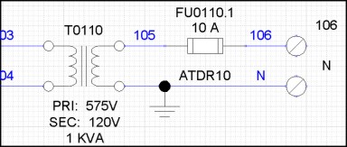
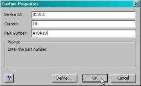
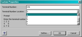
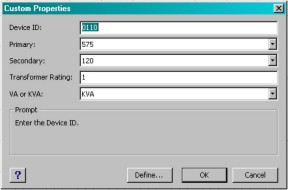
As
the example below shows, each device has a number of custom properties
associated with its symbol. When a symbol is dropped on the drawing
page from the stencil, the custom properties window is displayed, allowing
the user to modify the contents immediately. These properties can be
modified at any time by double-clicking the symbol. Symbols are
"locked" to prevent inadvertent changes to sizing or text fields.
|